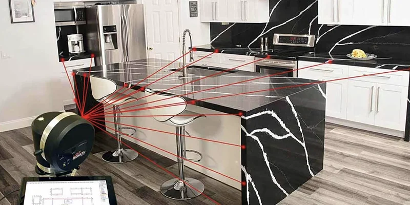
Digital countertop templating connects field measurement, digital geometry, DXF files, slab imaging and fabrication planning within a coordinated stone-fabrication workflow. Instead of treating site measurement, slab placement and production as completely separate stages, digital systems can carry verified countertop geometry from the jobsite into compatible CAD, slab-layout and fabrication environments.
This workflow is particularly useful for custom stone countertops where walls may not be perfectly square, islands require several fabricated pieces, sink and cooktop openings must be positioned accurately, or the visible movement of granite, marble, quartzite and other patterned materials needs to be considered before cutting begins.
Digital technology does not replace fabrication experience, project verification or physical inspection of the stone. Its primary value is in preserving usable geometry between stages and providing a controlled environment in which component placement, seams, material utilization and production requirements can be evaluated before the slab is cut.
Technical scope: This guide summarizes commonly documented digital stone-fabrication workflows. Equipment capabilities, software functions, file formats and production procedures vary between manufacturers and fabrication businesses.
Table of Contents
Digital countertop templating is the process of recording the geometry required to fabricate countertop components and converting those measurements into digital drawing data that can be reviewed and transferred into later stages of production.
Depending on the project and measurement system, the field process may record cabinet lines, finished walls, corners, angles, countertop edges, overhangs, sink and appliance openings, backsplashes and other reference points that influence the size and shape of the finished pieces.
A digital template is therefore more than a list of measurements. It can represent the actual relationships between points, lines, angles and component shapes within a coordinate-based drawing. That geometry can then be prepared for compatible CAD, slab-layout and fabrication systems.
The exact information depends on the project and equipment being used, but digital countertop geometry may include:
Fabricators may use laser measuring systems, portable digital measuring equipment, physical templates or combinations of different methods. The important requirement is not simply whether the project is measured digitally, but whether the approved geometry accurately represents the conditions on which fabrication will be based.
Digital templating and digital slab layout are closely related, but they answer different questions.
Digital templating establishes the required dimensions and shape of the countertop components. Digital slab layout determines where those approved component shapes should be positioned on the material from which they will be fabricated.
This distinction becomes especially important with natural stone. A countertop component can be dimensionally correct while still producing an undesirable visual result if it crosses an unwanted feature of the slab, changes the direction of strong veining between adjoining pieces or creates a poor visual transition at a seam.
Connecting digital geometry with material planning allows these questions to be considered while the slab remains uncut.
A modern digital countertop workflow can be understood as a sequence of controlled information transfers rather than a single measuring operation.
The advantage of this workflow is continuity. Geometry recorded during templating can become the basis for later drawing and layout operations without requiring every countertop component to be reconstructed repeatedly from written measurements.
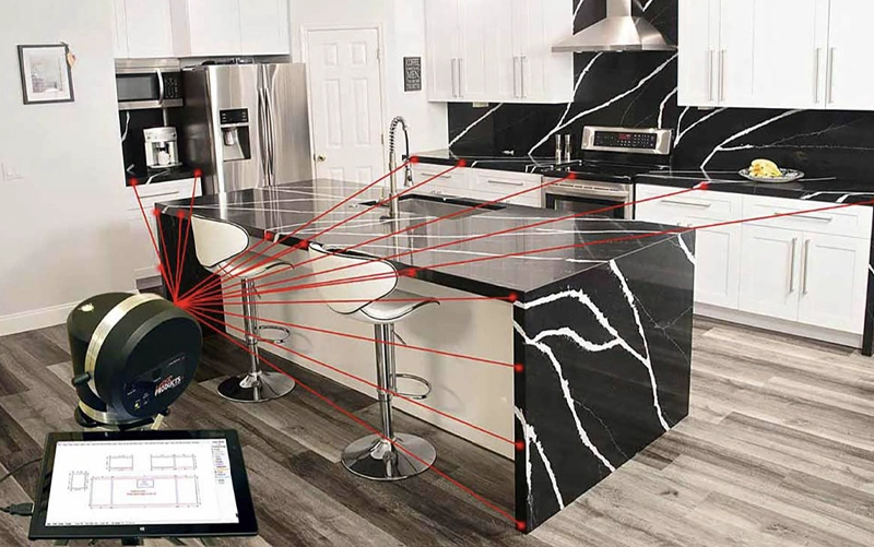
Accurate digital measuring equipment cannot compensate for measuring conditions that later change.
If cabinetry moves, an appliance specification changes after templating, a sink model is replaced or another relevant site condition changes, an accurate digital recording of the earlier conditions may no longer represent the geometry required for fabrication.
Digital measurement therefore depends on both measuring accuracy and appropriate project readiness. Technology records geometry, but fabrication professionals must still determine which project conditions should govern the finished work.
DXF stands for Drawing Exchange Format. Within stone-fabrication workflows, DXF is commonly used to exchange two-dimensional drawing geometry between compatible measurement, CAD, slab-layout and production systems.
A DXF file may contain linework representing countertop perimeters, sink or appliance openings, separate components and other drawing geometry. Digital measuring systems used in the stone industry can export measured geometry in DXF format so that compatible software can use the drawing without manually recreating every component from a dimension sheet.
| DXF Can Represent | DXF Does Not Automatically Confirm |
|---|---|
| Countertop component outlines | That field conditions have been correctly approved |
| Sink or appliance opening geometry | That appliance specifications are final |
| Lines, arcs and other CAD geometry | That every element is production-ready |
| Separate countertop components | That seam and edge decisions are finalized |
| Geometry transferable between compatible systems | That no additional CAM or machine programming is required |
A DXF file should therefore be understood as a representation of geometry rather than a finished countertop or automatically approved machine file. Dimensions, units, openings, offsets, seams and other fabrication requirements may still need to be checked before production.
Once countertop geometry has been established, the selected stone can also be represented digitally for layout planning.
A fabrication-oriented digital slab is different from an ordinary photograph used only to show the appearance of the material. Specialized slab-imaging systems can produce a calibrated digital representation that maintains a meaningful dimensional relationship with the physical slab.
This allows countertop geometry to be evaluated against the material at an appropriate scale.
Digital slab imaging is particularly useful with granite, marble, quartzite and other natural stones because each physical slab contains its own combination of veining, mineral movement, colour variation and localized visual features. Even slabs from the same material selection can be related without being visually identical.
Depending on the software and imaging workflow, a digital slab can help the fabricator evaluate:
Digital imaging does not replace physical slab inspection. Natural stone can contain characteristics that require direct evaluation. The digital representation is primarily a planning tool that allows dimensional geometry and visible slab information to be considered together.
This stage directly connects digital countertop templating with material planning.
After countertop geometry has been prepared in a compatible digital format, slab-layout software can import the shapes representing the required components. When DXF is used as the exchange format, those countertop shapes can be positioned over a calibrated digital representation of the physical slab.
Field measurement → countertop geometry → DXF → digital slab image → component placement → reviewed layout → fabrication preparation
Within the layout environment, individual countertop components can be moved and, where appropriate, rotated to compare different positions before cutting begins.
Changing a component’s location on the digital slab does not change its approved dimensions. It changes the location and orientation from which that component would be cut from the material.
For example, a large island may be positioned so that a prominent vein passes through a preferred area of its visible surface. A smaller perimeter component may be placed in another part of the slab. Components that will meet at a seam can also be evaluated together before the cutting arrangement is finalized.
Digital slab layout therefore brings two distinct forms of information into the same planning environment:
Commercial stone-fabrication systems document workflows in which DXF countertop layouts can be overlaid on digitally captured slab images.


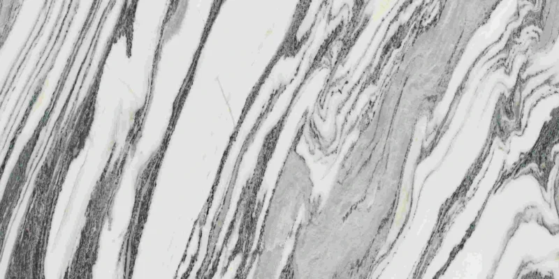

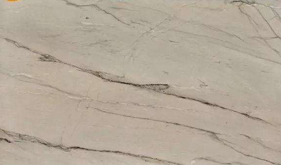
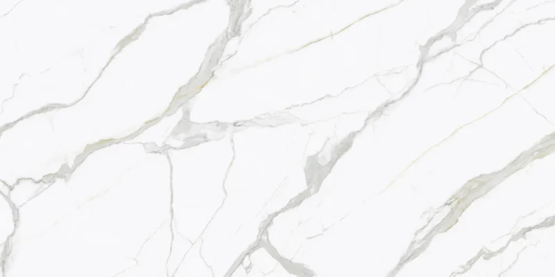




Many countertop projects require more material than a single slab can provide. Large kitchens, oversized islands, waterfall ends, full-height backsplashes and multi-room projects may require several slabs.
Digital slab-layout systems can support multi-slab planning by allowing required countertop components to be evaluated across multiple digital slabs rather than treating each slab as an isolated layout problem.
This is useful when the available slabs contain related but non-identical movement. Different arrangements can be compared before determining which countertop components should come from each slab.
Material utilization must also be considered. Selecting the most visually dramatic area for every component can consume unnecessary stone or leave insufficient material for another required piece. Conversely, optimizing only for maximum yield may create unwanted changes in pattern direction or weaker visual relationships between adjoining components.
Multi-slab planning is therefore a balance between material efficiency, visual continuity and fabrication requirements rather than simply an automatic nesting exercise.
On directional marble, quartzite, granite and other visually active materials, changing the position or orientation of a component can substantially affect the finished appearance.
A prominent vein may run along the length of an island in one position and across it in another. Likewise, the orientation selected for a perimeter piece may influence how its movement relates to an adjoining return, backsplash or waterfall panel.
Digital slab layout allows these alternatives to be compared while the material remains uncut.
A countertop seam is both a technical joint and a visual transition. Digital layout can help evaluate which parts of the stone would meet at a proposed seam and how the material’s visible movement may transition between the adjoining pieces.
Visual continuity is not the only consideration. Component dimensions, fabrication limits, transportation, access to the installation area, cabinet support and installation conditions can all influence where a seam can practically be located.
Digital slab layout is therefore most useful for comparing the visual effect of technically viable seam arrangements rather than selecting seams based on appearance alone.
Different slab layouts can produce different levels of material utilization. One arrangement may conserve more usable stone, while another may consume additional material to preserve a preferred vein relationship or visual composition.
Neither approach is automatically correct for every project. The appropriate balance depends on the material, component geometry, available slabs, fabrication requirements and agreed visual priorities.
Digital slab layout should therefore be considered a decision-support stage rather than simply an automated nesting process.
After the countertop geometry and slab layout have been reviewed, the project can progress from planning into fabrication preparation.
CAD and CAM perform different but related functions. CAD systems are used to create, review or modify geometry, while CAM and machine-programming systems translate approved geometry into instructions suitable for production equipment.
Depending on the fabrication environment, this may involve bridge saws, CNC saws, waterjets or CNC machining centres.
DXF geometry can form part of this workflow, but the presence of a DXF file does not mean the component is automatically ready to cut. Production preparation may still require confirmation or definition of:
Stone-production software can use DXF geometry as part of slab nesting and cutting preparation, while compatible workflows may also export completed slab-layout geometry for later saw or CNC programming.
Digital templating reduces repeated manual interpretation of geometry, but it does not eliminate the need for quality control.
Errors can still occur when incorrect conditions are measured, project specifications change after templating, digital drawings are prepared incorrectly or information advances to production without appropriate review.
Typical quality-control checks may include:
Physical stone inspection also remains important because digital slab imagery cannot necessarily reveal every surface or structural characteristic relevant to fabrication.
Digital and physical templating methods can both be used to establish countertop geometry. The appropriate approach depends on the project, available equipment and the production workflow used by the fabricator.
| Consideration | Digital Templating | Physical Templating |
|---|---|---|
| Geometry | Recorded as digital measurement data | Represented through a physical pattern |
| CAD Transfer | Can move directly into compatible digital workflows | May require digitization or recreation |
| DXF Workflow | Compatible systems can export DXF geometry | Requires an additional digital conversion stage |
| Digital Slab Layout | Component geometry can enter compatible slab-layout software | Physical geometry must first be converted into digital form |
| Production Continuity | Can preserve the same geometry through several digital stages | May require additional transfer or interpretation steps |
The main advantage of digital templating appears when the measured geometry can continue through drawing, material layout and fabrication planning without unnecessary reconstruction of the same shapes.
Digital countertop templating is the process of measuring the geometry required for countertop fabrication and recording it as digital drawing information that can be reviewed and transferred into compatible CAD, layout or production systems.
Yes. Digital measuring systems used in the stone industry can export measured countertop geometry in DXF format. The file can then be used by compatible CAD, slab-layout or production software.
Yes. Specialized digital slab-layout systems can combine imported countertop geometry with a calibrated digital representation of the physical slab. This allows individual component shapes to be positioned and evaluated against the material before cutting.
Yes. Multi-slab layout can be used to evaluate how countertop components should be distributed across several available slabs while considering material use, pattern relationships and fabrication requirements.
No. Digital layout provides tools for visualizing and comparing possible arrangements, but the final result still depends on the selected slabs, component geometry, viable seam locations and fabrication judgment.
Not necessarily. DXF transfers drawing geometry, but additional CAD/CAM review and machine-specific preparation may be required before cutting or machining begins.
The technical concepts described in this guide are supported by documentation from manufacturers and software developers serving the stone-fabrication industry.
Technical note: Digital measuring systems, slab-imaging equipment, CAD/CAM software and fabrication machinery do not all use identical workflows. The processes described in this guide represent documented examples of digital stone-fabrication practice and should not be interpreted as a mandatory production sequence for every countertop project.